Photo3D Tutorial Guide
This guide was written for introducing readers to basic operations
of the Photo3D system. The goal is creating a 3D model of a building
with texture mapping starting from two sample photo images.
1. Getting started
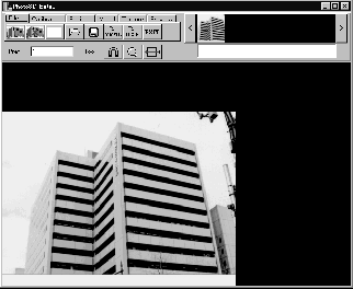
Double-click on the Photo3D icon, then a window like the following figure
appears.
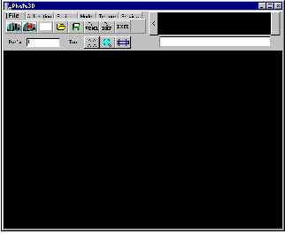
figure 1.1
At the top of the window, there is a set of menu tabs. The File
tab is selected by default.

figure 1.2
2. Adding photo into project
Click on Add Photo button, then there appears a file selection
dialog box to select a file of photo image to be imported into the project.
Select "midou1.bmp" in "test_images" folder and click on [Open] button.
 Add Photo button
Now let's add the second photo "midou2.bmp", similarly as the first
one. The image in the main drawing area is replaced with the second one.
It is the lower half of the same building.

figure 2.2
|
The thumbnail of the second photo is enclosed by a rectangle line colored
in bright blue, showing it is currently selected.
|
Changing the current photo

figure 2.3
|
Click on the thumbnail of the first photo (the left one), then the
blue rectangle moves to it indicating the current photo, and the first
photo is redisplayed in the main drawing area.
|
3. Creating the upper half of the building
3.1 Calibration
In this section, we determine the directions of three axes (x, y and z)
of 3D space relative to the photo image, using the tool called "frame lines".
Click on the Calib tab to go to calibration mode. In this
mode the menu and the main drawing area are like the figure 3.1.1. and
3.1.2. Confirm that the MOVE button is pushed down. Other buttons
except the COLOR button are irrelevant here in this tutorial. Please
leave them untouched for now, in order not to be confused.

figure 3.1.1
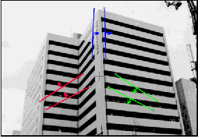
figure 3.1.2
|
In the main drawing area, three pairs of line segments (six lines)
are drawn overlapped against the background image. Each pair is colored
in red, green and blue, respectively. We shall call them "frame lines",
because these lines determine the framework of the 3D space. They
are expected to indicate the x, y and z directions by being fitted to
edges in the image parallel to the directions.
|
Moving frame lines
Moving ends of frame line
At each end of the frame lines there is a small circle. Click on one of
the circles and drag the mouse without releasing the mouse button. Then
the end point of the frame line moves.
Carrying frame line
You can also carry a frame line by clicking and dragging the short arrow
at the midpoint of the frame line.
Move the frame lines as shown in the figure 3.1.3. See also "Tips
for quick and precise fitting" in the Photo3D User's Manual. (section 2
Calibration)
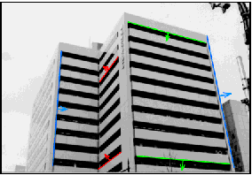
figure 3.1.3

figure 3.2.1
 Initialize #-cursor
 |
 Create a Rectangle
 |
 Move #-cursor
 |
 Create a Point ***
 |
 Rotate #-cursor
 |
 Create a Polygon ***
 |
 Move an edge of #-cursor to a point
 |
 Delete a Polygon
 |
 Move #-cursor to a line
 |
Buttons with asterisks*** are not used in this tutorial |
We create 3D models, here, using the photo as the background image.
We also use the user interface tool called "#-cursor" (sharp cursor) to
indicat positions in the 3D world.
This "#-cursor" is a rectangle supposed to be placed in the 3D world
space and displayed on the screen overlapped against the background image.
We can move each of its four sides independently. It is also possible to
rotate the "#-cursor" around one of its sides as the axis of rotation.
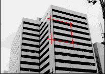
figure 3.2.2
|
Click on Initialize #-cursor button, then the "#-cursor"
appears.
|
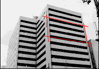
figure 3.2.3
|
Drag the right side of the cursor so that it fits to the right edge
of the front wall of the building.
|
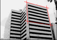
figure 3.2.4
|
Drag the upper side of the cursor so that it fits to the top edge of
the front wall of the building.
|
Magnifier
The left edge is not so clear as the right and top edges. We use the "Magnifier"
tool to precisely adjust the left side. Push the Magnifier button
in the tool bar, then a red square appears near the center of the drawing
area, and an auxiliary window (Magnifier window) appears, where the portion
of the image in side the red square is displayed magnified.
 Magnifier
button
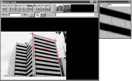
figure 3.2.5
Drag the red square to the top left corner of the front wall.

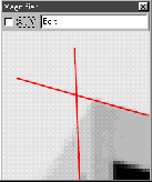
figure 3.2.6
Enter a small value such as 0.1 or 0.01 in the prefix window.
A small value keeps the movement of the cursor slow, thus you can adjust
the side of the cursor to fit the corner precisely.
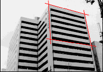
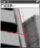
figure 3.2.7
Similarly, adjust the lower side of the cursor to fit the edge as shown
in the figure 3.2.7. The reason why we particularly choose this height
is "by cutting at this height, the entire upper half part of the building
is included in this photo, while the entire lower half is included in another
photo."
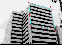
figure 3.2.8
|
Click on Create Rectangle button, then a rectangle is created
where the "#-cursor" is placed. It is colored in cyan.
 Create Rectangle button
|
Creating the next wall
To create the wall left to the front one, we must first rotate the "#-cursor".

figure 3.2.9
|
Push down the Rotate #-cursor button, then you will see the
button lowered and the value "90" is displayed in the prefix window indicating
that the angle of rotation is 90 degree. (You can edit this value in order
to specify another amount of rotaion. However, in this tutorial you don't
need to edit this value.)
|
Click on the left side of the "#-cursor", then it rotates 90
degree around the picked side.
 |
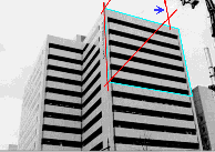 |
| figure 3.2.10 |
figure 3.2.11 |
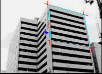
Drag the nearer side of the cursor (indicated by blue arrow in the
figure 3.2.11) to the concave edge of the building.
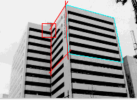 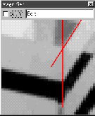
figure 3.2.12
|
|
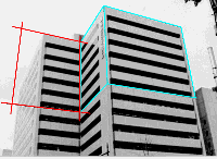
figure 3.2.13
|
Create a rectangle by clicking on the Create Rectangle button.
Then rotate the "#-cursor" again by pushing the Rotate #-cursor
button and clicking on the concave edge as the axis of rotation.
|
Go on the similar operations until four walls are created.

figure 3.2.14 |

figure 3.2.15 |
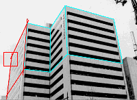
figure 3.2.16 |

figure 3.2.17 |
Now that you have created the upper half model of the building, it
is a good timing to save the project. Click on File tab and Save
Project button, then a file selection dialog box appears to indicate
the file name to save the project.
We recommend you to create a new folder to save your project, because
Photo3D outputs several files together with the project file. The file
name extension for Photo3D project file is ".p3d". You may omit the extension,
then Photo3D automatically adds the extension. For example, if you specify
"test1" for the project name, it is saved as "test1.p3d".
Copies of the added images are also saved in the same folder as the
project file, with name such as "test1_midou1.bmp". If you have defined
texture mapping, the texture image files are also saved in the same folder
with names such as "test1_nnn.bmp" where "nnn" is a number generated by
program.

figure 3.2.18
 Save
Project button
Loading project
The saved project can be loaded again using the Open Project button.
The photo images are loaded from the copied ones saved in the same folder
as the project file.
 Open
Project button
4. Creating the lower half of the building

figure 4.1

figure 4.2
|
Change the current photo to the second image by clicking on the right
thumbnail. Then go to the calibration mode by clicking on the Calib
tab.
|
Move the frame lines, similarly as we did with the first photo.
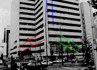
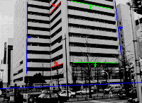
figure 4.3
Unlike in the case of the first photo, we need this additional step
before starting the modeling.
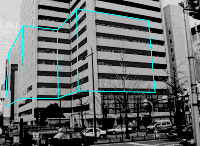
figure 4.4
|
Click on the Model tab as a trial. You will see the polygons
of the upper half of the building, which we have created in the previous
steps. But it doesn't fit to the background image. It is not surprising,
because we have not yet indicated the positional relation between the first
photo and the second one. We have not indicated even where is the origine.
Instead, we have merely indicated the directions of three axes x,
y and z, by fitting the frame lines to edges in the image for each of the
two photos in the "Calibration step". Fixing the relative position between
the two photos is the goal of this step.
|

figure 4.5
Go to "Positioning" step by clicking on the Position tab.
 Push the Screen-parallel Move button,
then you go into the "Screen-parallel move" mode, where the previously
created model is moved parallel to the screen. Push the mouse button anywhere
in the main drawing area, and drag the mouse. Then the model moves to the
same direction as the mouse.
Choose a certain feature point in mind. Adjust the position of the feature
point of the model, so that it overlaps to the corresponding point in the
background image. For example, choose the lower right corner of the model
and adjust the position as shown in the figure 4.6.
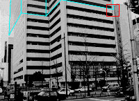
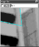
figure 4.6
The feature point is fitted, however the size of the model is a little
too large compared to the background image. We consider that this
is because the model is placed too near to the eye. So we need to push
the model away from us. Before pushing the model, we must fix the feature
point, which we have adjusted, not to move (at least on the screen).
Fixing the target point
|
|
Push the Target button, and click on the feature point in the
model.
|
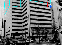 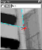
figure 4.7
|
Then a small red mark appears at the selected point of the model. This
point will be fixed in the next step moving model in depth direction.
|
Moving model in depth direction
|
|
Push the Depth Move button, then you will go into the
"Depth Move" mode.
|
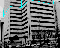
figure 4.8
|
Push the mouse button anywhere in the main drawing area and drag the
mouse. If you push the mouse away from you, then the model moves away with
the target point fixed on the screen (as if you are playing the tronbone).
|
Creating the lower half of the model

figure 4.9
 Initialize #-cursor button
|
|
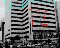
figure 4.10
|
It should be noted that the "#-cursor" is placed at some arbitrary
depth by initialization, although it looks as if it lies on the front wall.
In fact, in this case, it lies a little behind the wall.
|
The point of this section is an exact positioning of "#-cursor" relative
to existing elements. (rectangles of the upper half of the building, in
this case) There are two functional buttons for this purpose:
 :
Move to point button
 :
Jump to line button
Both of them consists of two steps:
-
Select one of four sides of "#-cursor"
-
Select the target point/line where the selected side should be moved to.
They differ from each other as the following:
-
A point must be selected for the first one, while a line
for the second one.
-
The first one moves only the selected side of the cursor, while
the second one moves the whole cursor as a rigid body.
Adjusting "#-cursor" to a line
Push Jump to line button, then click on a side of the "#-cursor"
as prompted in the message window below the thumbnail window.

figure 4.11
Click on the upper side of the "#-cursor".
If you fail to click on, an error message in red letters appears in
the message window accompanied by a sound of warning.

figure 4.12
If you successfully select, the selected side turns to brighter red
(shown in yellow in the figure 4.13), and the message changes as shown
below, prompting you the next action.

figure 4.13
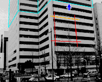
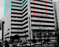
Click on the bottom side of the rectangle (indicated by a blue arrow
in the figure 4.14), then the "#-cursor" moves to the position shown in
the figure 4.15. It is guaranteed that the upper side of the cursor and
the bottom side of the rectangle are exactly at the same position.
 |
 |
| figure 4.14 |
figure 4.15 |
Adjusting other edges
Push Move to point button, and click on the left side of the "#-cursor"
according to the prompt message. Next, click on the point indicated by
blue arrow in the figure 4.16. Then the selected side of the cursor moves
to the indicated point without changing the positions of the other three
sides of the cursor.
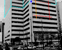
figure 4.16
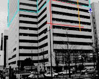
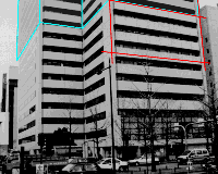
Similarly, move the right side of the cursor to the right edge of the
wall by clicking on the lower right corner of the rectangle as the target.
 |
 |
| figure 4.17 |
figure 4.18 |
As for the bottom edge of the front wall, it is not clear in the image.
Drag the lower side of the cursor to some specious position.
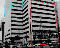
figure 4.19
Create a rectangle there by clicking on the Create Rectangle
button. Rotate the cursor by pushing the Rotate Cursor button and
click on the left side of the "#-cursor".
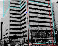
figure 4.20
Adjust the other side to the concave edge of the building. Be sure
to use Move to point button instead of dragging by mouse in order
to place it exactly at the same position as the upper half model. Next,
create a rectangle.
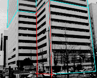
figure 4.21
Rest of the model
It would be easy to finish the rest of the model, using the following three
functions repeatedly:
-
Rotate the "#-curosr"
-
Move a side of the "#-cursor" by Move to point button
-
Create a rectangle
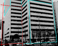 |
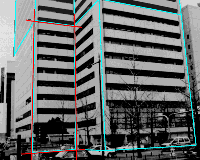 |
| figure 4.22 |
figure 4.23 |
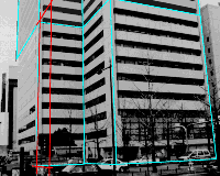 |
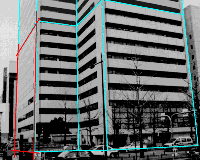 |
| figure 4.24 |
figure 4.25 |
Go to texture mode by clicking on the Texture tab. And go back
again to the first image.

figure 5.1

figure 5.2
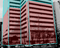
Click on any position inside the rectangle of the front wall. Then
it turns to red, showing it is defined texture mapping. Similarly click
on the rest of the four walls of the upper half of the building.
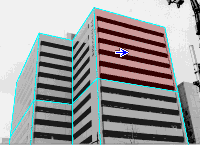 |
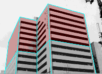 |
| figure 5.3 |
figure 5.4 |
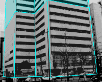
Go to the second image, then you will see the four rectangles that
you have defined textures are colored in blue, showing that they are given
textures from an image other than the current image. Define textures to
the four walls by clicking on each of them.

figure 5.5
 |
 |
| figure 5.6 |
figure 5.7 |
Click on the Preview tab.

figure 6.1
-
Rotate
-
Horizontal move
-
Vertical move
-
Look around
-
Zoom
and
from left to right.
Rotate
Push Rotate button. Then click anywhere in the main drawing
area and drag. By horizontal drag, the model rotates around the vertical
axis. By vertical drag, the angle of depression varies.
Horizontal move
The model moves horizontally.
Vertical move
The model moves vertically.
Look around
You can look around with the position of your eye fixed
Zoom
Move the mouse nearer to you to zoom in. Conversely, move the mouse
farther from you to zoom out.
Texture mode
Push the mode button. Then the mode changes into texture mode,
and the button face changes to represent the current status. To return
to wire frame mode again, click on the button once again.

figure 6.2
Last modified May.10.1998




![]() Magnifier
button
Magnifier
button


![]() Open
Project button
Open
Project button


![]() Push the Screen-parallel Move button,
Push the Screen-parallel Move button,


